| |
Contents | EBJ Home | Single molecule measurements and biological motors |
Myosins are non-processive or weakly processive motors. This has implications both for the way in which experiments are performed, and for the interpretation of the resulting data. Similar considerations will apply to other non-processive motors, or transient intermolecular interactions. We also briefly discuss processive motors.
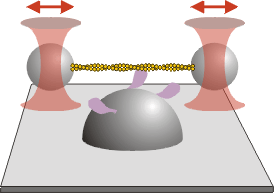
Because the myosin typically remains bound to the actin filament for a short period of time, it will diffuse away rapidly unless it is held in close proximity. For this reason, in most trapping experiments with myosins, two trapped beads are used, with an actin filament extended between them (see figure).
These “bead pairs” or dumbbells are assembled from a fluorescent actin filament and two beads coated with an actin binding protein. As for motility assays, the fluorescent label is usually rhodamine phalloidin. For the actin binding protein, we usually use the HMM fragment of myosin, treated with NEM (N-ethyl maleimide), which binds irreversibly to the actin filament. Other possibilities include gelsolin. A filament is “captured” from solution using the trapped beads (see video).
 |
||
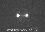
| A pair of fluorescent 1 μm polystyrene beads with a rhodamine–phalloidin labelled actin filament suspended between them, visualised by epifluorescence microscopy. | ||
The flow cells in which trapping experiments are performed are similar to those used in motility assays, except in two significant respects. Firstly, the myosin concentration required to observe individual interaction events is much lower than for sliding motility. Secondly, “pedestals” are needed to raise the myosin above the surface. This is because the trapped beads are typically 1 μm in diameter, and need to be separated from the cover slip surface, so that the actin filament will be a μm or more above the surface. For pedestals we typically use 1.7 μm diameter silica beads. The whole surface, including the beads, is coated in nitrocellulose, which is also what sticks the beads to the cover slip.
 |
||
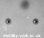
| Bright field view of an actin-bead assembly interacting with a myosin coated “pedestal”. | ||
The next video shows how the assembled “bead pair” is offered up to the myosin coated “pedestal”. (The actin filament is not visible in bright field). The smaller dark circles are the two trapped beads; the larger one is the surface “pedestal”, coated in this case with rabbit skeletal myosin. The positions of the traps, and of the stage, are shown by computer generated cursors. The video shows the following:
This illustrates the principle of making single molecule recordings. The surface density used in practice would be lower, and the bead positions would be recorded using some form of position sensor.
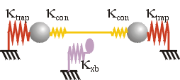
The stiffness experienced by a trapped bead in this arrangement depends on whether the motor or other protein is bound to the cytoskeletal filament. In the detached state, the stiffness in the x direction, i.e. along the filament axis, is simply twice the trap stiffness, κtrap. Since the stiffnesses of the actin filament itself, and of the filament-bead linkages, are typically much higher, they do not significantly affect the behaviour of the system.
On the other hand, once the motor is bound to the actin, typically the stiffness becomes a composite of the trap, motor and connection stiffnesses. The filament stiffness is much higher and still does not play a role.
The connection stiffnesses, κcon, are of the same order as the motor stiffness, κxb. Because these stiffnesses are in series with the motor stiffness, this makes it difficult to obtain accurate measurements of motor stiffness and force. This is known as the series compliance problem, and several elaborations of trapping methodology have been developed to overcome it:
Most actomyosin experiments are done in free-running or displacement mode, where no forcing functions are applied. The challenge then becomes to detect the interaction events in these records. We have recently reviewed the current methods for analysing optical tweezers data (Knight et al., 2001), so we shall present only a brief summary of the problem, and various solutions, here.
The information we would like to extract from interaction events includes:
The displacement can be obtained from the mean displacement of a large set of events. The kinetics of the rate-limiting step(s) for myosin dissociation (usually ATP binding) can be obtained from an exponential fit to the event lifetimes. By averaging many events together, we can learn about the rise time of displacement, or sub-steps or other processes occurring during the events.
For all of these, particularly 2 and 3 above, it is essential to be able to determine the start and end points of events with good time resolution.
When myosin binds to actin, there are two separate effects which can be seen in a displacement record:
Some non-variance based methods for using the change in stiffness to detect interactions exist; for example the correlation method or the use of high frequency sinusoids.
These effects are illustrated by the trap simulation applet on the next page.
A wide range of methods have been used to analyse optical tweezers data of non-processive motors. Here is a brief summary (see our review for more details).
Most of the myosins that have been studied using optical tweezers are non-processive; in contrast, most kinesins are processive. Recently, myosin V was shown to be processive (Mehta et al., 1999; Veigel et al., In Press), and some non-processive kinesins have been identified.
Processive interactions in the optical tweezers appear as a displacement “staircase”, with sequential displacement events. The starting position for the steps in such a staircase is known, and therefore the power stroke can be obtained directly. The first step, however, is subject to the same uncertainty as non-processive motors.
Because of the large displacements produced by processive motors, the restoring forces can become quite large and will affect the rate of any load-sensitive steps in the motor's kinetic cycle. Ultimately, the motor will stall. Alternatively, a “force clamp” feedback mechanism can be used to track the motor over long distances and under different loads.
| Contents | Next |